Metro construction
Metro plays a very important role in contemporary urban agglomerations. As a result of the expansion of the metro line, more and more people decide to travel to work, not by car but by metro.
In addition, underground construction of the subway, not interfering with overground infrastructure, offers extremely efficient access to many points of the city.
Metro is very popular in Western Europe. The largest one is located in London – it has 270 stations which length 420 km. Unfortunately, this type of geotechnical construction still matures in Poland. There are already 2 lines in Warsaw, of which the second is currently being expanded.
First line runs from Młociny to Kabaty. The second line, from the Daszyński Rondo to the Wileński Railway Station and now is being expanded in the east and west directions. It is also planned to expand the third line – running to Gocław.
Tunneling technology
In a dense urban agglomeration, the works are planned with the least interference
in an infrastructure. Vertical walls are made, the risk of settling near excavations is limited, and if it is possible – as in the case of subway construction – the method of underground drilling is used. In Warsaw was used the technique TBM (Tunnel Boring Machine) type EPB (Earth Pressure Balance) was used, the balancing of soil pressure. This technology shows a low probability of subsidence and the possibility of a high control of drilling parameters.
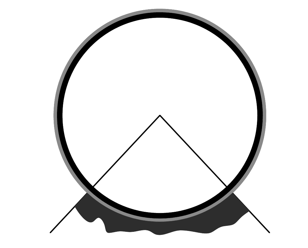
The tunnel is drilled with a rotating TBM disk that is hydraulically moved forward. However, drilling the shield is not enough. In the front there are nozzles that can give water, plasticizers, foam or concrete – depending on the problem encountered before the disk. Behind the dial there are such devices as: meters, magazines, aggregates, pumps, ventilation systems, etc., which are responsible for failure-free operation of the TBM machine.
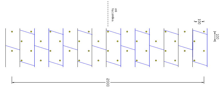
After the tunnel is drilled, rings (consisting of five tubings) are placed and one wedge, as a sixth element which is pressing.The wedge, because of the pressure, tightens all joints and gives rigidity to the construction. Between the wall of the tunnel and the ground, there is a gap, which is filled with binding and sealing mortar. The mortar stabilize the ground and ensure the tightness of the tunnel.
The general outline of the comma
Between the tunnels, there are also connections called ventilators, separated from each other by approx. 300 m. Implementation of the connector (“commas”) is a real problem due to the difficulty of moving from one tunnel to another through “bare” ground. Depending on the geological conditions, suitable technology for stabilizing the ground between tunnels is selected, which may be, for example, freezing or jet-grouting injection columns. Unfortunately, not everything can be predicted, which causes many implementation problems, because in such a complex geotechnical project, there is a risk of many failures. Such a failure occurred on the construction site of the II-nd metro line in Warsaw, near the Daszyński Rondo, in the tunnel D09 on connector D09.1.
Technology od comma production + geology
In the case of the D09.1 connector, the jet-grouting jet injection technology was chosen. The breakdown took place by traditional mining methods. 120 columns were made, 8-9 m long and 1.5 m in diameter, in the net of an equilateral triangle with side 115 cm, in the entire area where the puncture is to be found. Soil conditions indicated the interbedding in sandy clay from fine sand with a thickness of 2 to 3 meters. The comma bottom is on 18 m. P. P. T.
 Technology of sealing the comma
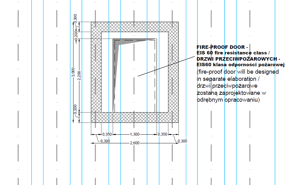
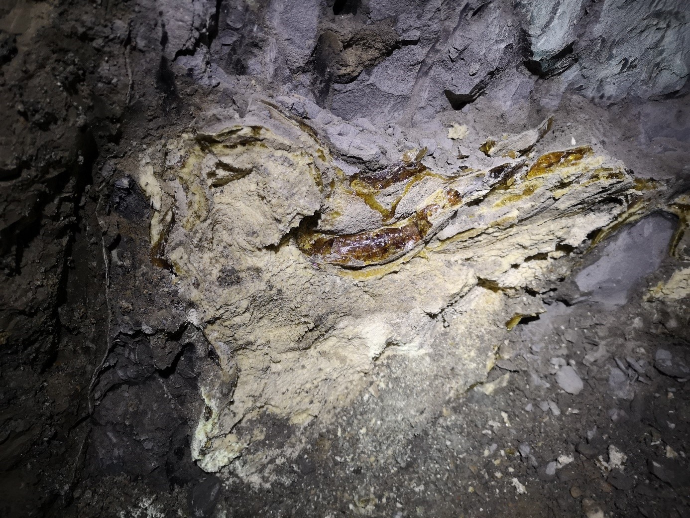
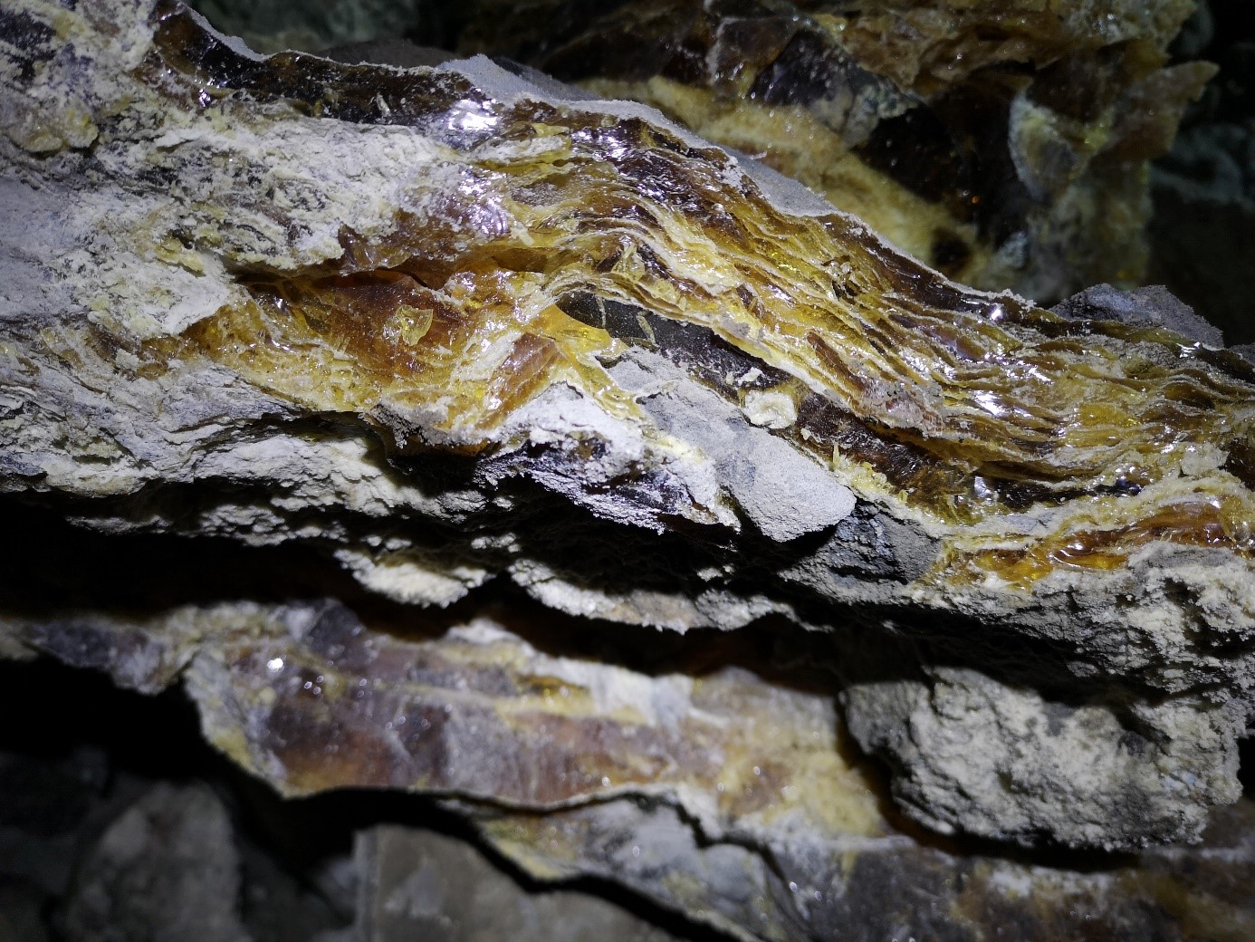
Before starting any drilling work, the project recommends sealing the windows with a pressure injection method. For this purpose, holes (perimeter of the comma) are made, perpendicular to the tunnel surface, at a distance of about one meter from the window of the connector. The distance between the holes is selected in such way that when pressure is given – the circles of the resin divergence overlap. As an injection material used a single-component, foamable, low-viscosity polyurethane resin . This resin is designed to fill and seal the space behind the tubing around the window commas, at the interface with the ground, creating a stiff conglomerate of sand and resin with closed pores.
Execution of control bores from the right tunnel side
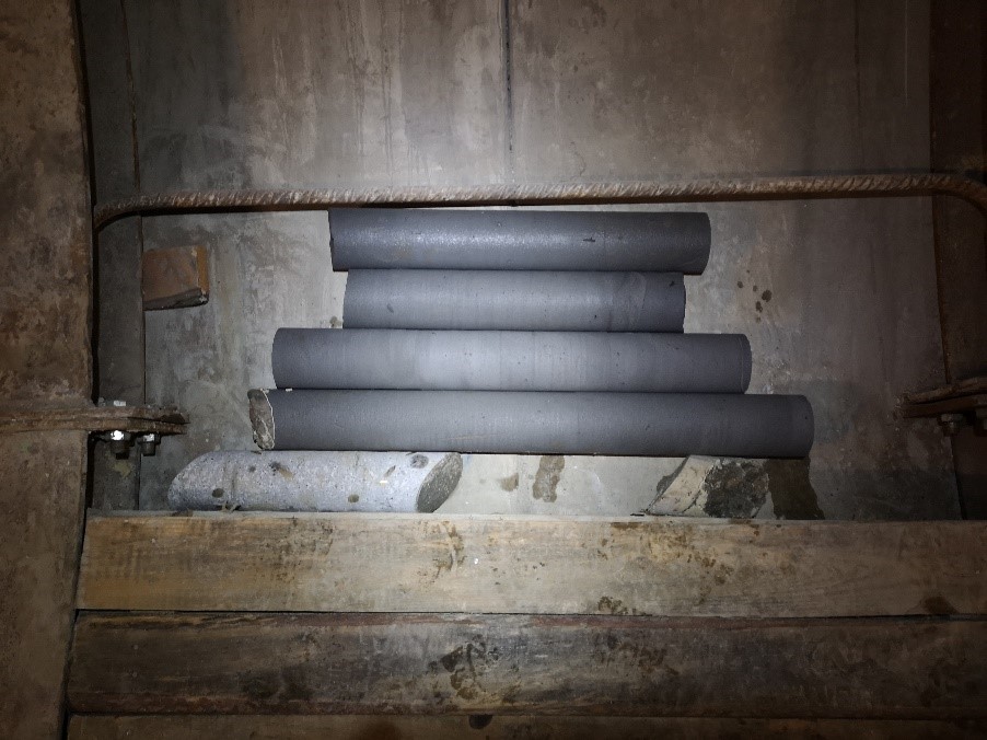
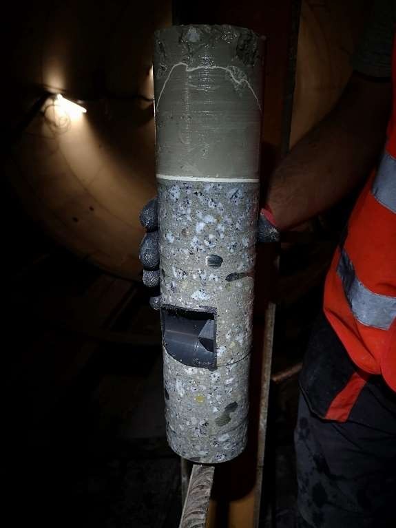
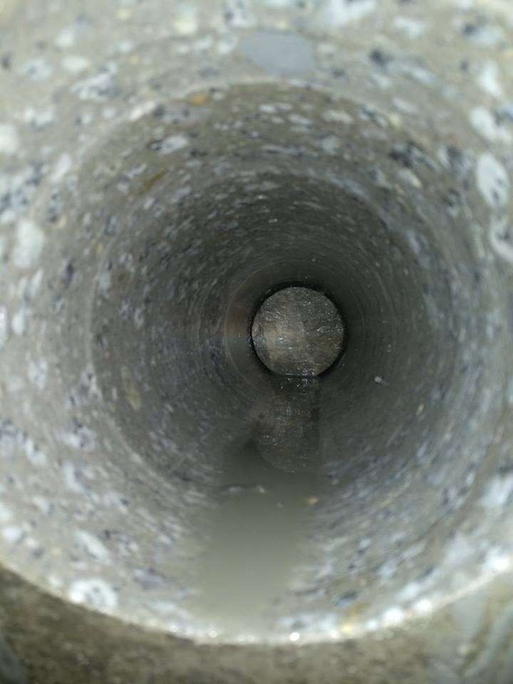
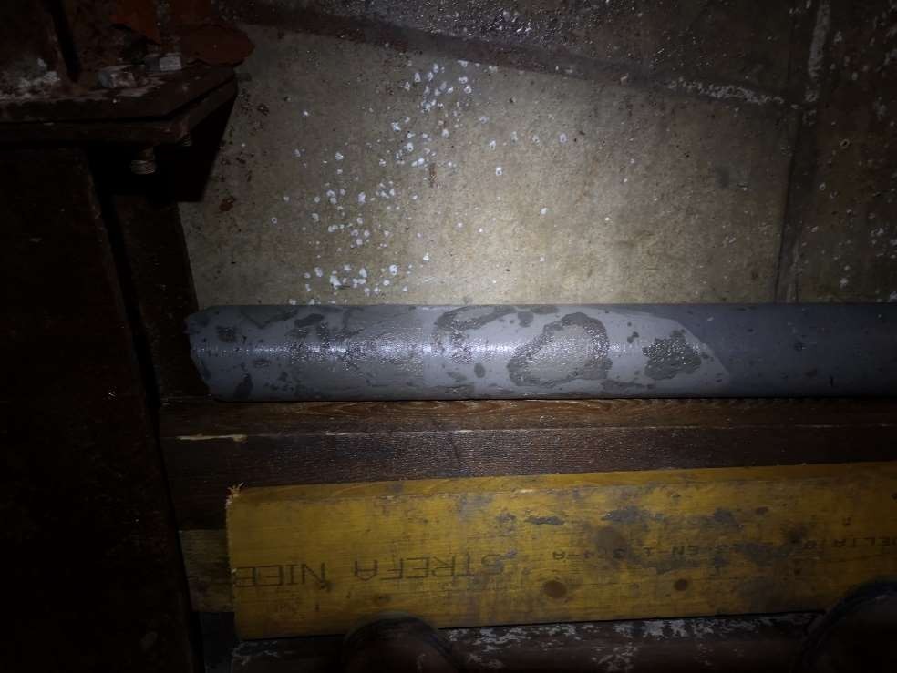
After the injection seals, core drillings were made to check the condition of the ground behind the wall. The core drillings, ordered by GW (with an inner diameter of 100 mm), were aimed to take the injection made from TBM and recognize the ground conditions between the tunnels. As agreed, 3 wells were drilled with a length of 4 m:
of which the injection and core samples were effectively obtained, showing the state of the soil after stabilization by the jet-grouting method.
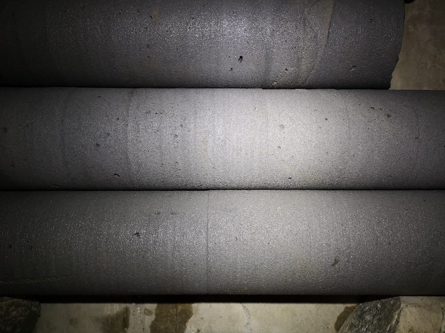
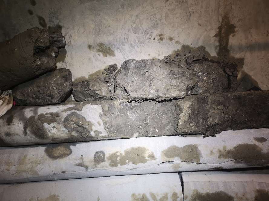
Upper hole: the core is mostly monolithic, with small interstices of clay and sand along the entire length, blocking the outflow of water and cuttings. After drilling the well, a slight drainage of groundwater from the well was observed.
Center hole: obtained a sample of the injection and about 3.5 m of the ground core reinforced by the jet grouting method. The drilling was quite smooth. There were interbedding of clay and sand at a depth of more than 2.5 m, but in a smaller amount than was the case in the upper well and temporary problems with the flow of cuttings (caused by interbedding). After drilling the well, slight drainage of groundwater from the well was observed.
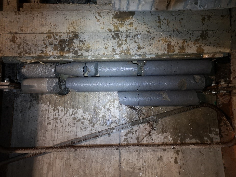
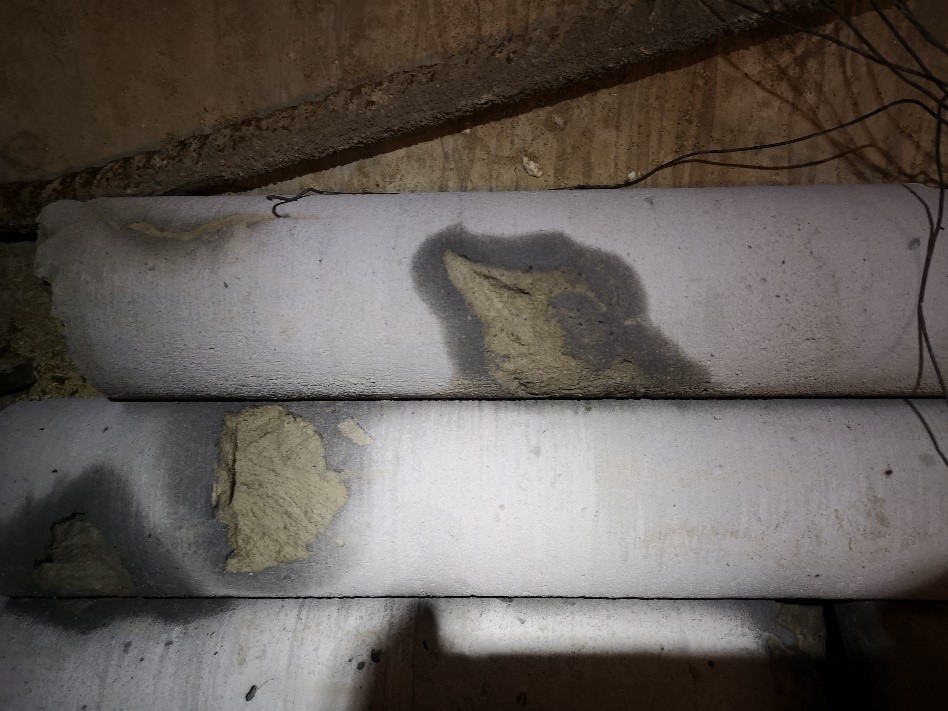
Lower hole: a 4 m long borehole was drilled in the lower edge of the planned piercing. The TBM sample was taken and the core with a total length of approx. 3.5 m. The well was drilled without any disturbances. The sample of the injection was collected and the cores of the reinforced soil were monolithic and uniform, with no visible discoloration. After drilling a small leakage of water (filtration) was revealed.
Execution of control bores from the left tunnel side
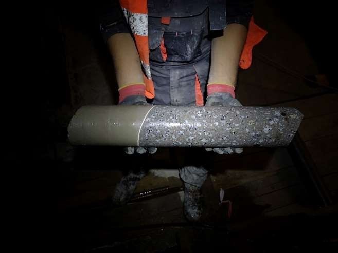
After good results of the right side of the tunnel, a truncated version of previous wells was selected. In this case, the option of 4 m boreholes was abandoned in favor of 2 m lower commas and one, 4 m high commas. Meters were obtained from metric holes as in the drawing. It shows tubing concrete as well as TBM injections. In the following part there was a ground stabilized by the jet-grouting method.
In the middle of the upper edge of the planned breakthrough, a 100 mm diameter borehole was drilled, 4 m long. A sample of the injected and about 3 m of the ground core reinforced with the jet-grouting method was obtained. The remaining part of the core was destroyed during the borehole and attempts to remove the material from the core drill bit. During the drilling, no interstices of fine loose soil or voids were encountered. The borehole was run smoothly, and the outlets that emerged did not indicate any inconvenient deviations.
After a few days of observation of unsealed holes, no inflow of ground water was found.
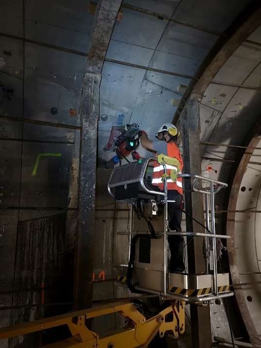
Start of working + breakdown
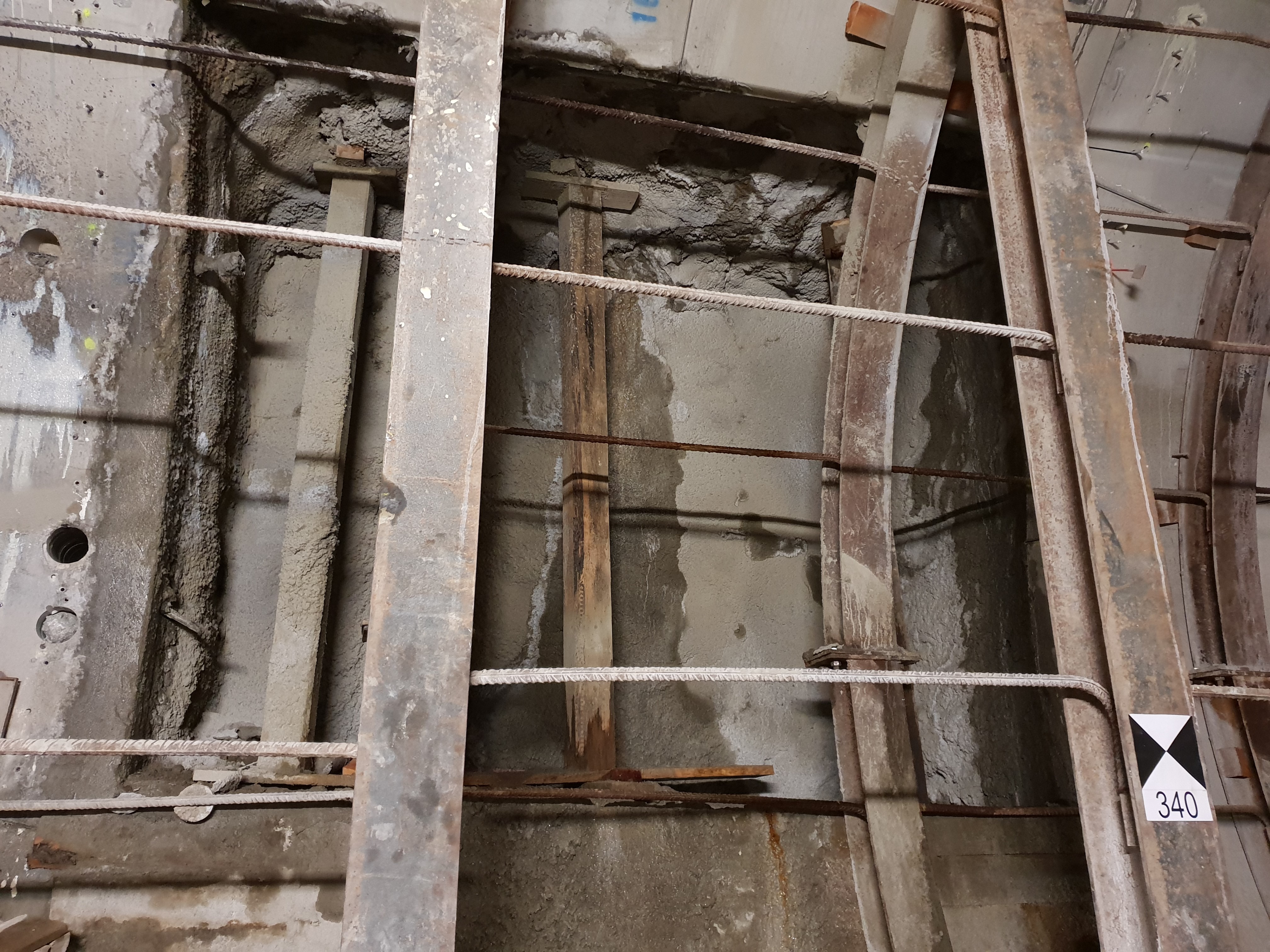
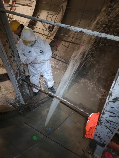
The first stage of works consisted in cutting out the comma’s circumference in the tunnel. Then forging started. After forging reinforced concrete tubings, it was undertaken to drill in a conglomerate of soil and jets. As a rule, drilling takes place in stages. In the morning, the forging begins, and at noon, inserting the frames and throwing the shot-out part – the thickness of the frame – with a shotcrete.
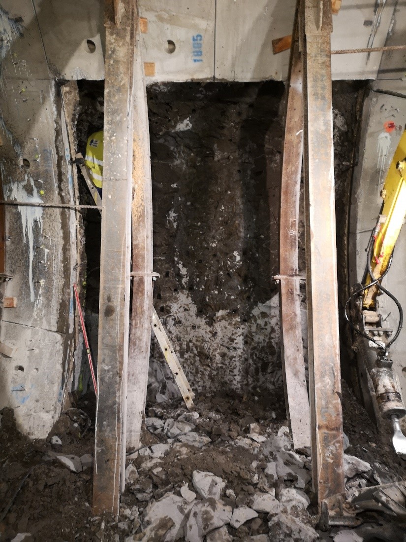
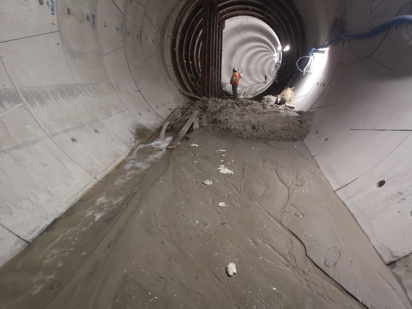
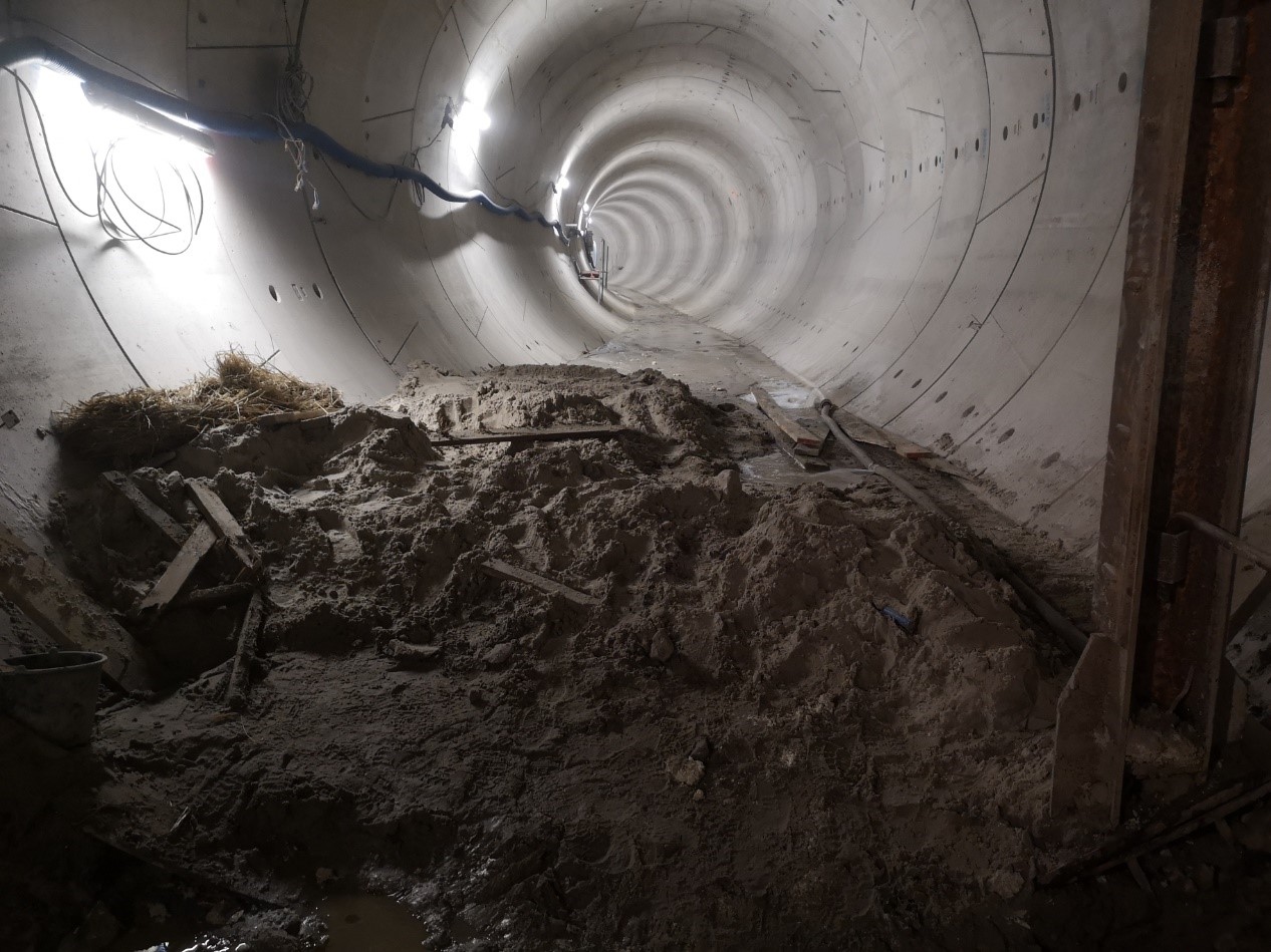
After forging more than a meter in the ground, before mounting the first frame, a small infiltration of water in the bottom of the comma was noticed. Those who were supposed to start gunning planned to clean the loose sand substrate for a better shotcrete base. After a few shifts in the bottom, infiltration of water began increase rapidly, carrying large amounts of fine sand behind it. The leak was tried to stop with sandbags, but to no avail. The water flowing out from under the connector, taking more and more sand, creating a corridor for even more water and soil. In the lower left corner of the comma a PVC pipe was installed, leading the largest flow into one place. Immediately a decision was made to make a concrete shelf, which stopping the water from the connector, except the PVC pipe. As a result of these actions, after obtaining sufficient strength, the leak was stopped through the pipe and the flow of one-component polyurethane resin was injected, completely stopping the infiltration of water into the tunnel. The leakage was blocked at 1:40 the next day.
Analysing the failure
The probable cause of the failure was the insufficient (in this place) overlap of the jet-grouting columns and the inflow of water from the sandy soil layers. It was feared that as a result of a breakdown, the tunnel connector could damage the utilities network and settle buildings in the area above the connector. Four CPT tests were commissioned in the area of failure. The aim of the research was to check soil compaction and compare new tests with tests from before the failure. The research cone has stopped in the sand layer, which means its significant compaction. The effect of these activities was the inability to further study the conditions of the ground at the depth of occurrence of the connector.
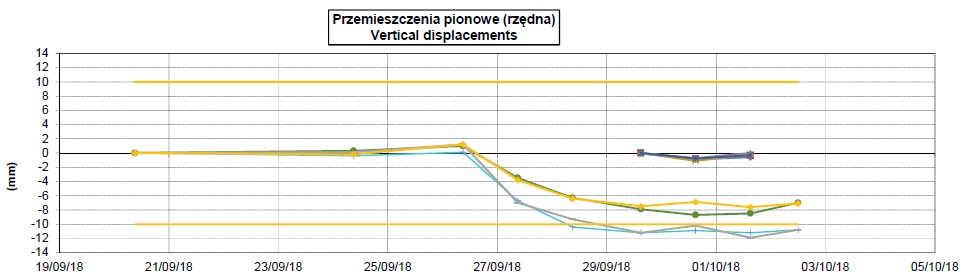
The next step was laser scanning of the tunnel, which was to determine the settlement of the structure. A georadar survey was also carried out in the area of the bottom of the tunnel and in the lower part of its walls. The results of the georadar indicated loosening the soil at a distance of 10-15 m in both directions of the tunnel. Of course, the results should be treated only as a guide due to the attenuation of electromagnetic waves through the segments and the sealing layer. Measurements of land benchmarks indicated the subsidence of the ground at 7 mm !!! The maximum settlement of nearby buildings was 3 mm. The settling of the tunnel was on the level of 10-14 mm, at a length of about 10 m. Luckily, tubing was not unsealed. The results after the failure stabilized and no other damages were noted.
The determination of the scope of the failure was made by calculating the volume of washed sand. A very high result of 25.4 m3 of the soil and huge amounts of water in the tunnel were obtained. The failure and its consequences generated many problems, including stopping other works in the tunnel and the need to take further steps to perform the breakthrough. It was necessary to perform the injection strengthening and stabilizing the ground.
Control bores after the failure
After the failure, a further 4 m test bore was made. 100 mm diameter boreholes were preceded by 22 mm diameter inspection holes to minimize the risk of water or loose soil entering the tunnel. Two monolithic cores were collected from two wells with small sand layers. The holes did not splash. No water infiltration was observed. The last, third well was made near the place of failure. About 2.2 m of the core was obtained, which disintegrated during extraction from the drilling crown. The well was drilled smoothly until it reached a depth of 3 m. A layer of clay was found there, which was drilled to about 50 cm. Clay, although mixed with the material used to reinforce the soil, was plastic. No inflow of groundwater from the well was observed.
Technologia naprawy
Repair technology
The help of the repairing the failure was addressed to us. A team of COVER specialists, after analyzing all data, developed the following assumptions:
Three ethaps of injection
The injection repair was divided into three stages:
Ethap 1 included injections at the comma and in the bottom of the tunnel near the comma, spreading maximum 10 m in both directions from the comma axis. First, a filling filled with Chemopur material was used. Lances were embedded in the bottom of the tunnel, in a grid, about 1 m, passing by. In order not to damage the gaskets, the boreholes were not drilled in the gaps between the tubings.
Ethap II. In the lower zone, around the dimensions of the connector, Chemopur material was introduced to create a conglomerate with a circle of 1 m, larger than the size of the connector. Lances were embedded in the wall, in a grid, every 60-70 cm in a passing way. In the bottom, lances with a diameter of 14 mm and a maximum length of 0.5 m were used, in holes 18 mm. In contrast, lances with a diameter of 14 mm and a length of 2 m were used in the cut, in 25 mm holes. Assumed grid of holes at intervals of 60-100 cm.
Ethap III. The final stage was the structural injection. For this purpose, a single-component HA Soil injection resin with a longer setting time was used and less viscosity, whose task is to fill all the minimum voids and cavities.
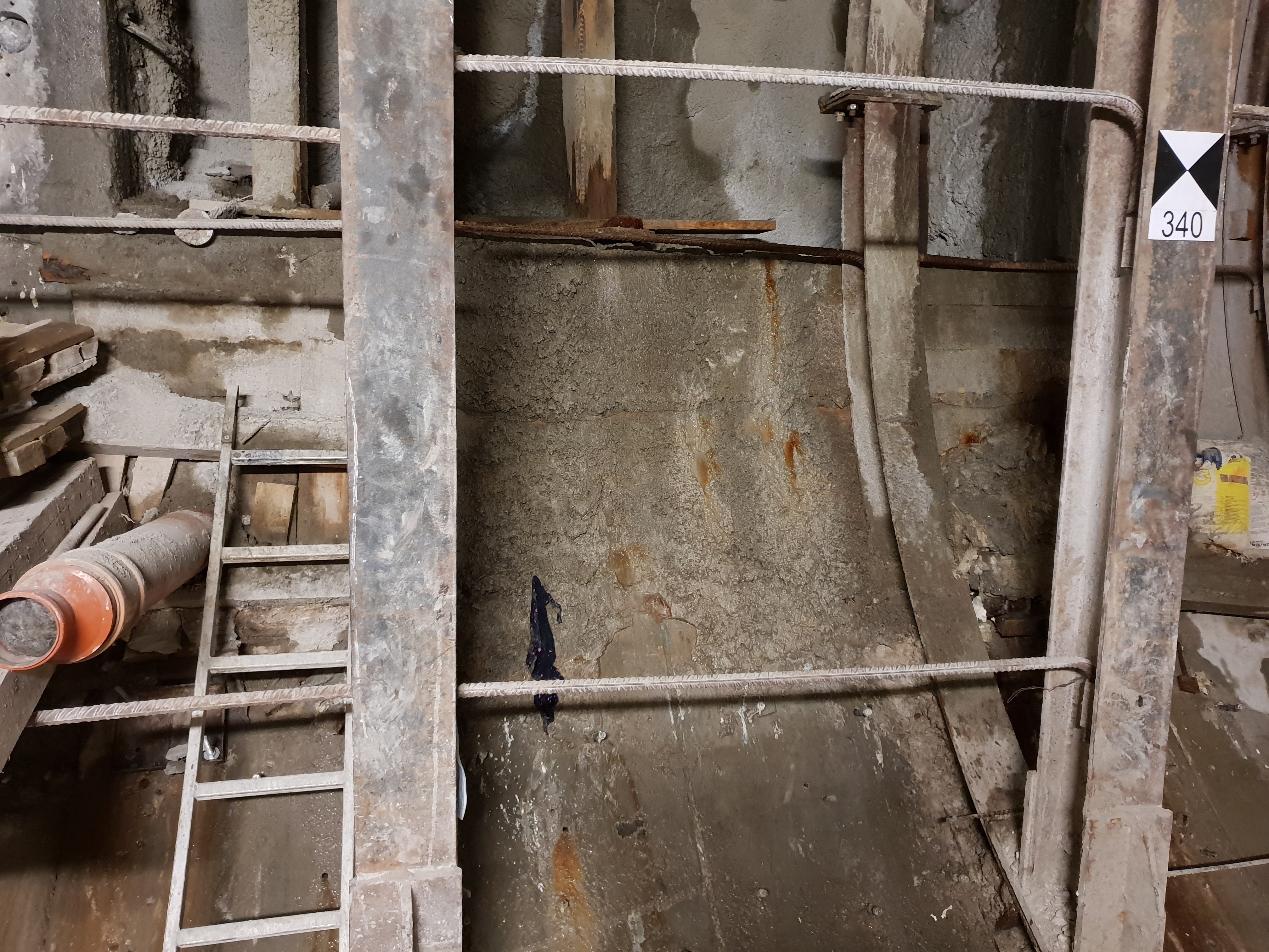
All injection stages were successful. During drilling of the first stage very large cavities under the bottom and high water pressure were observed. During the injection, nearby packers were opened to make sure that the material is moving and gives the seal a certainty. The injection was carried out from the comma axis in both directions. 5.5 tonnes of Chemopur resin and 300 kg of HA Soil were used to perform the repair of the connector.
Summary
After the injection, further drilling was started. GW decided to mount the frames in the connector every 0.5 m, not every 1.5 m – as originally planned. Before each drilling stage, the control wells were drilled 2 m forward. Until the end of the breakthrough no large spills were observed. In the breakthrough zone, there were zones and voids filled with resin.
The presented problem shows how complex and difficult is to break through two tunnels. Geotechnics can surprise, that’s why it is worth to invest in technology that ensures the correct and timely performance of work, and most importantly – it will ensure people’s safety and reduce the negative effects of work on the surface of the earth. All soil research and displacement results are very helpful, because they give a fresh look at the situation.
Due to the difficult conditions of work and the complexity of the problem, it is necessary to plan the repair program well and strategically with the selection of the appropriate equipment, material and technique. The human factor is also an important issue – experienced specialists know how to solve it effectively and professionally.


